HaldInc
VelocityX 2026
Click image to play video
One of the kids got a Nerf gun for Christmas. Not one of those that looks like a killer machine, but a unicorn blaster.
This one:

After a few shots, the question from my kids arose: How fast is it actually shooting?
I quickly asked the kids back, “Good question—how could you find out?”
Suggestions:
- 1st suggestion: We can record the sound of firing it into a wall at a known distance and measure the time between the shot and it hitting the wall.
- 2nd suggestion: We can record a video of the dart passing by and count the frames.
- 3rd suggestion: We can shoot it past two switches and measure the time difference.
All good suggestions, mainly from my 9- and 13-year-olds.
Proof of concept:
We decided to proceed with the 3rd suggestion, but use optical sensors instead of switches, as they provide a non-invasive measurement—and I already had a bag of old H21A1 sensors.
PoC circuit setup—just some resistors for current limiting of the sensors. All the other stuff on the board was for another project.


We made a quick proof of concept and printed a holder for the two optical sensors with a spacing of 100 mm. This was really a “dirty setup,” but that’s how PoCs sometimes are, and it was good enough to show the kids that we could measure it with our “standard household tools.”
The two optical sensors were hooked up to their respective oscilloscope channels with rising-edge triggering. Even with this simple setup, we could clearly see that the time between the dart passing the first and last sensor was 4.66 ms. As the flight distance is 100 mm, this corresponds to 21.46 m/s. We got our first speed measurement!
Product design:
Now that the PoC worked, we decided to turn this into a real product look and feel. …naturally not for sale—unless someone wants to buy it :) We started with the requirements and the constraints:
Requirements:
- Non-invasive measurement
- High accuracy measurement
- Show current, minimum, maximum, and average speed
- Standalone tool—no need for external power, phone, or PC connection
- 3D-printed case
- Some cool-looking light
Constraints:
- This is a Christmas holiday project with the kids—only limited time.
- Use only components we have at home; no time to order anything.
The sketch:

The velocity meter unit:
From the PoC, it became clear that the H21A1 phototransistor optical interrupt switch was producing some “noise” and was sensitive to the environment. The H21A1 is designed with a gallium arsenide infrared-emitting diode paired with a silicon phototransistor inside a small plastic housing, with only 3 mm between the emitter and the transistor. For our project, I needed a gap of about 25 mm, so I removed the diode and transistor from their original housing and built my own setup.
Even though the sensor is designed for infrared, ambient light could still interfere and affect the signal. To solve this, I covered the transistor in black tape and built a channel-like cover to shield the entire pathway between the first and second sensors. This helped stabilize the signal and made the setup more rigid.


The design speeds up print time while maintaining a lightweight yet strong structure. I designed the octagonal tube using the sheet metal tool in Fusion and printed it as a thin, foldable structure.


The fully covered channel turned out to have an even bigger benefit: making sure that no darts land inside the unit itself, but are guided through it.
Improving signal quality:
To improve the signal quality from the phototransistors, I added a hex inverter with Schmitt-trigger inputs (74HC14). This provides a clean, sharp level transition that is perfect for the microcontroller:

Power switch and the shutter assembly:
I wanted to have a mechanical power switch directly in series with the battery pack, so we have zero standby power consumption. As I would have a mechanical movement to power the unit on and off, I thought it would be cool to also make this cover the measuring pathway—as dust protection. Actually, just to make it look cool.
This turned out to be harder than expected, but I ended up with a design like this:


Here is the final printed version being installed.

As a side note, the LCD display is a very old 2 × 20-character Epson EA-D20025AR module that I salvaged from a fax machine years ago and have reused in several projects since.
Battery case:
If you can buy an off-the-shelf battery container, always do that! But if you really want to design and print it yourself, that is naturally also an option. This is what I needed to do, as I couldn’t wait for one to be delivered and didn’t have any at home.


Again, I ended up overengineering the front cover a bit too much 🙂
The first iteration had a screw locking the front cover. This design resulted in a bigger bump on the inner side that would collide with the moving shutters; therefore, I needed a new solution. I ended up with a solution that is more integrated into the rear panel itself.


Here are some renderings of the final design, featuring a print-in-place rotating disk for locking the panel.


This is the final printed version:

Light effect

To enhance the design and avoid just having a plain box, I wanted to add ribs to the sides—inspired by the M41A Pulse Rifle from Aliens. This idea quickly evolved into a different shape, and I decided to print them in semi-transparent PLA so we could add light to it.
The light effect has two functions:
- When the unit is powered on, the light rolls from one side to the other.
- When you shoot a Nerf dart through the velocity meter, the ribs on the sides light up as the dart travels through the unit.
This is a rendering of the ribs:

The kids wanted blue light, so that’s what we went with. Unfortunately, I only had blue SMD LEDs, so I needed to solder them under my microscope.

Some hot glue to hold it in place…

…and here’s the first test:

LCD display
As mentioned before, the LCD display is a very old 2 × 20-character Epson EA-D20025AR module that I salvaged from a fax machine years ago. Yep, it’s old 🙂 but still working.
Here, I used the LCD to show current, minimum, maximum, and average speed. As I only have two lines, the MCU updates the display every 4 seconds, alternating between showing current and average speed, and minimum and maximum speed.

Final design
The dimensions:

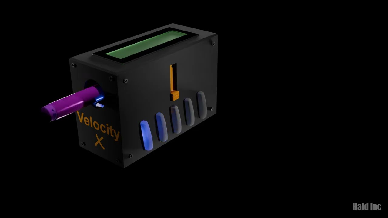
Render of the final design:

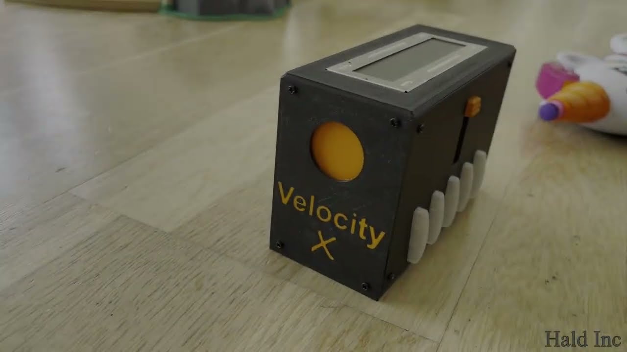
The real-life working product:

Conclusion on the speed:
When measuring the speed of a gun, the measurements are very stable, and you can see a clear difference between the two Nerf guns we have. The “Unicorn Blaster” has an average speed of around 21.5 m/s, while the other gun is around 26.8 m/s.
It is also clear that the largest impact on the speed is not actually the gun itself, but the dart. When it is old, stepped on a few times, and slightly bent, it reduces the speed significantly.
In a video I recorded, I used a dart that was squeezed a bit and had a few markings. This resulted in an average speed reduction from 21.6 m/s to 4.6 m/s.

Click image to play video
All CAD is design in Autodesk Fusion. Animations in Blender. All 3D print is done on my FlashForge Creater Pro II.